
Participants and ethical requirements
In total, 19 adult volunteers (15 male, 4 female) participated in the present study. All participants were free from any known allergic reactions to Kinesio tapes or adhesives, did not present with acute general illnesses or orthopedic conditions incompatible with participation, and were not pregnant at the time of data acquisition. The data collection campaign was conducted between September 1st and December 15th, 2024. Participants’ ages ranged from 22 to 55 years. For men, the mean age was 39.07 ± 10.44 years (range: 22–55 years), and for women, 34.75 ± 12.97 years (range: 25-53 years). Participant height ranged from 158 cm to 192 cm. Men had a mean height of 180.53 ± 6.33 cm (range: 171–192 cm), while women had a mean height of 163.75 ± 4.92 cm (range: 158–170 cm). Body weight varied between 52 kg and 102 kg. The mean body weight was 78.40 ± 11.33 kg for men (range: 62–102 kg) and 61.25 ± 11.64 kg for women (range: 52–78 kg). The Body Mass Index (BMI) ranged from 19.57 to 29.39 kg/m2. For men, the mean BMI was 23.98 ± 2.58 kg/m2 (range: 20.91–29.39 kg/m2), and for women, 22.76 ± 3.42 kg/m2 (range: 19.57–26.99 kg/m2).
All participants were fully informed about the experimental procedures, potential risks, and the intended use of the collected data. Written informed consent was obtained from all individuals prior to participation. The experimental protocol was reviewed and approved by the Ethics Committee of the Ulm University of Applied Sciences (approval date: April 18, 2024; reference number: 2024-01). The study is registered in the German Clinical Trials Register (DRKS) under the DRKS-ID DRKS00034705.
Acquisition Setup
The measurements were conducted in the motion analysis laboratory at the Ulm University of Applied Sciences. Participants performed the designated movement tasks on an h/p/cosmos treadmill. For walking tasks, the treadmill was activated, whereas for physiotherapeutic movements, it remained stationary. A safety bar attached to the treadmill in combination with a safety harness served as fall protection during walking activities. Additionally, a custom-built apparatus was mounted at the rear end of the treadmill, allowing the attachment of resistance bands with adjustable tension. This setup enabled participants to be positioned under tension, as required for the execution of the targeted physiotherapeutic exercises. The configuration of the resistance band system was adapted to each exercise type and adjusted individually for each participant.
Around the treadmill, 10 cameras were arranged as part of a Qualisys optical MoCap system. Of these, eight cameras were dedicated to marker tracking, while two RGB cameras recorded the performed exercises. An overview of the measurement environment is provided in Fig. 1.

Top view of the experimental setup including treadmill, safety equipment, resistance band frame, and camera configuration. Eight Qualisys cameras were used for marker tracking, and two RGB cameras for video recording.
To achieve comprehensive full-body kinematics, 33 reflective markers were attached to each participant (see Fig. 2). The marker arrangement was based on the established Institute of Orthopaedic Research (IOR) marker set, slightly adapted for our specific application needs. These adaptations involved the removal of several markers that conflicted with the placement of IMUs (markers on the toes and markers on the lower back) or essential safety equipment (markers on the upper back, the sternum and the fingers), preventing their proper attachment.
The Qualisys MoCap system recorded the spatial trajectories of these markers with the eight mentioned infrared cameras positioned around the participants, operating at a sampling frequency of 100 Hz using the QTM software (v2023.3). To ensure high-quality reference data for subsequent analysis, we carefully calibrated the Qualisys motion capture system following the manufacturer’s recommendations. Calibration was only accepted if the standard deviation of wand length measurements remained below 1 mm, indicating stable camera positioning and consistent marker detection across views.
Additionally, two RGB cameras recorded the performed exercises at 25 frames per second. The video recordings from these RGB cameras were used later to segment the individual repetitions of exercises and to precisely define the start and end points of each individual repetition.
In addition to the MoCap system, the used setup employed nine Xsens MTw Awinda IMUs, which were primarily placed on the lower limbs of each participant, as illustrated in Fig. 2. Each IMU recorded motion data at a sampling rate of 100 Hz using the MT Manager software (v4.6).

Anterior (left) and posterior (right) views of the experimental marker setup. IMUs are shown in blue, Qualisys markers used for segment pose tracking are marked in red, and Qualisys markers mounted on IMUs for optical orientation validation are shown in orange. Marker and sensor labels match the naming conventions used in the dataset. Note that the IMU placed on the right forefoot is labeled as XSens_Hand_Right, since the standard Xsens setup does not include a dedicated IMU for this position. Therefore, the otherwise unused right-hand IMU was repurposed for the right forefoot.
Orientation estimation was performed onboard on each sensor using the proprietary Xsens Kalman filter algorithm (XKF3hm), which computes the orientation of the sensor’s local coordinate system (CS) relative to an estimated Earth-fixed reference frame. The computed orientation data were transmitted wirelessly to a central recording PC. To enable validation of the IMU orientation estimates, a custom sensor mount was designed to attach four reflective Qualisys markers directly to each IMU. The IMU on the right forefoot carried only three markers due to space constraints (see Fig. 2). This configuration allowed the IMU orientation to be independently derived from the optical motion capture system, facilitating a comparative analysis of IMU-based and marker-based orientation estimates.
Temporal synchronization of the measurement systems was ensured through sync units provided by Xsens and Qualisys. The Xsens sync unit acted as the master device, supplying a measurement frequency and signals marking both the beginning and end of each measurement. This setup ensured precise synchronization and simultaneous data acquisition by both measurement systems.
Acquisition protocol
Over a period of four months, 19 participants performed two physiotherapeutic and two gait-related movement tasks while equipped with the described sensor setup. Each participant performed the movement tasks in a predefined, non-randomised order, which corresponds to the sequence listed in Table 1.
The physiotherapeutic exercises were selected from treatments commonly employed for addressing foot drop. The first physiotherapeutic exercise “Resisted Dorsiflexion” (RD) aimed at strengthening the muscles involved, particularly emphasizing the dorsiflexion of the foot. An adjustable resistance band was used to tailor the training intensity for each participant (depicted in Fig. 3). The tension was adjusted according to the participant’s individual strength and range of motion by the supervisors. The second physiotherapeutic exercise “Resisted Gait Simulation” (RGS) aimed to induce training effects within the context of a natural gait cycle. The core task involved executing half a gait cycle, with resistance bands providing additional muscular stimulation to improve gait stability and alleviate foot drop (depicted in Fig. 3).

Overview of the physiotherapeutic exercises and their execution variants. Both exercises are performed in a standing position. The first exercise RD is illustrated in the upper row, and the second exercise RGS is illustrated in the lower row. For each exercise, the first image from the left illustrates the standardized start position. The second image depicts the correct execution according to physiotherapeutic guidelines. The remaining three images on the right display common erroneous movement patterns observed in individuals with foot drop. Detailed descriptions of the respective deviations can be found in Table 1.
To gather sufficient data for identifying typical errors in exercise execution, healthy participants without foot drop performed four variations of each exercise during this campaign. One variation corresponded to the correct (textbook) execution, while the other three represented common movement errors observed in patients with foot drop. The individual variants are shown in Fig. 3 and are further described in Table 1. Prior to data collection, participants received structured instruction on all four movement variants. Each variant was first demonstrated by the experimenter, after which participants were given the opportunity to practice the corresponding movement under supervision. During this familiarization phase, participants received immediate corrective feedback whenever deviations from the intended execution occurred. Recordings were only initiated once participants demonstrated consistent and reliable performance of each variant. To minimise the potential influence of fatigue, participants were instructed to take a brief rest after completing each exercise variant, corresponding to ten repetitions per set.
The first gait-related task “Normal Gait” (NG) involved capturing participants’ natural walking patterns on a treadmill at three different speeds. Given the absence of physical impairments, a natural gait pattern with healthy variations was expected. Each participant performed the walking task at three self-selected treadmill speeds, recorded consecutively for approximately one minute each. Starting from an individually chosen baseline speed, the treadmill velocity was increased twice in small increments, resulting in a total speed difference of approximately 1 km/h between the slowest and fastest condition. The exact duration and magnitude of each increment varied across participants and can be retrieved from the corresponding timestamps_… file (see Fig. 6). The second gait-related task “Gait with Orthosis” (GWO) followed an identical protocol (including the same individual chosen treadmill speeds) but required participants to wear a knee orthosis on the right knee, restricting knee flexion to 0° (see Fig. 4).

Illustration of the two gait-related tasks. The left image shows a participant walking on a treadmill during the NG condition, without any assistive device. The right image depicts the same participant performing the GWO task under otherwise identical conditions, while wearing a rigid knee orthosis on the right leg that restricts knee flexion to 0°.
At the beginning of each recording session, participants were instructed to assume a standardized reference posture, a T-pose with legs abducted (see Fig. 2), to facilitate subsequent model calibration. After holding this static pose briefly, they proceeded to perform the respective motor task. The sequence of exercises followed during the session is detailed in Table 1, which also provides descriptions of each task and the corresponding aliases used in the dataset.
Postprocessing
In the following, we outline the postprocessing procedures applied to the collected dataset.
Notably, temporal synchronization between the Qualisys MoCap system and the Xsens IMUs is achieved by hardware-synchronization using dedicated synchronization units. This ensures temporal alignment during recording.
From the RGB video recordings, task-specific timestamps were manually extracted. For the physiotherapeutic exercises, we annotated the start and end of each individual repetition. In contrast, for the gait trials, we documented the start and end times of each walking speed condition.
The assignment of exercise repetitions to its corresponding variant (e.g. correct, toe lifted, etc.) was based on the verbal instructions given to the participants during data acquisition and subsequently verified through manual inspection of the video data by a supervisor. Since the labels were derived directly from the instructed exercise variants rather than from independent manual annotation, the labels should be interpreted as reflecting the intended exercise condition rather than a qualitative assessment of the movement execution.
The raw data from the Xsens IMUs and the optical motion capture system are provided in unaltered numerical form. However, data is not stored in the native export formats of the respective acquisition software. Instead, all data was converted into a unified, human-readable CSV format to facilitate usability and downstream processing. During this conversion, no filtering or modification of the underlying measurements were applied. However, naming inconsistencies, such as non-standardized IMU identifiers introduced by the original acquisition software, were harmonized to ensure consistency across all recordings. Marker trajectories from the Qualisys system were likewise preserved in their raw form. The assignment of marker labels was performed manually based on the experimental setup and subsequently validated for anatomical plausibility. In cases where a marker was not tracked for a certain period, no interpolation or gap-filling was applied. Instead, a placeholder value of 0.0 was inserted for the x, y, and z coordinates. All time series share a common, synchronized time base.
Inverse Kinematics using IMU Data and Musculoskeletal Models
To enable intuitive visualization and interpretation of the recorded motion data, we performed musculoskeletal simulations using the open-source software OpenSim (v.4.4.1). Based on the raw IMU orientation data, we computed joint angle trajectories that allow reconstruction of the captured movements within a biomechanical model. This approach facilitates a human-interpretable representation of the recorded exercises, without the need to share video recordings, which may raise privacy concerns and potentially violate participant data protection rights. In addition to the raw data, we provide all necessary files required to reproduce these simulations and visualizations within OpenSim, including subject-specific scaled models and processed IMU orientation data. All processing steps are transparently documented and fully reproducible using the accompanying GitHub repository, which contains code and configuration files to replicate the simulations from raw inputs.
In the following, we describe the underlying procedure in detail. Specifically, marker trajectories from the MoCap system were used to perform subject-specific scaling of the generic musculoskeletal model. However, the actual Inverse Kinematics computations were carried out using the IMU orientation data. This strategy was chosen to enable visualization of orientation-based IMU measurements, which are otherwise difficult to interpret in isolation. Nonetheless, users who prefer a marker-based Inverse Kinematics workflow may do so using the provided marker trajectories.
As a first step, a subject-specific scaling of the musculoskeletal model was performed for each recording using the OpenSim ScaleTool. This process adjusts the geometry of each body segment based on the recorded marker positions, thereby tailoring the model to the individual participant’s anthropometry. We used a full-body model originally published by Rajagopal et al.8 as the anatomical basis and adapted it to our experimental requirements. These adaptations included the integration of our custom Qualisys marker setup and the removal of joint motion constraints to ensure that the recorded IMU-based movements could be visualized without artificial restrictions. For the scaling process itself, we used the static calibration data obtained during the T-pose, which each participant performed at the beginning of each measurement. The calculated static posture was defined as the model’s default pose.
In the subsequent step, joint angle trajectories were estimated using the IMUInverseKinematicsTool provided by OpenSim. To enable this computation, it is essential to determine the static rotational offset between each IMU and its corresponding body segment in the musculoskeletal model. This transformation ensures that the time-varying orientation estimate calculated by the IMUs can be meaningfully interpreted in the context of the model and used as input for the Inverse Kinematics algorithm. The required transformation \(\begin{array}{c}XKF3hm\\ Segment\end{array}T\), which maps the orientation estimated by the XKF3hm algorithm to the coordinate frame of the corresponding OpenSim segment (Segment), can be expressed as follows:
$$\begin{array}{c}XKF3hm\\ Segment\end{array}T=\begin{array}{c}OpenSim\\ Segment\end{array}T\cdot \begin{array}{c}OpenSi{m}_{y}\\ OpenSim\end{array}T\cdot \begin{array}{c}XKF3hm\\ OpenSi{m}_{y}\end{array}T$$
(1)
Each component of the transformation is defined as follows: \(\begin{array}{c}XKF3hm\\ OpenSi{m}_{y}\end{array}T\) is a fixed transformation aligning the y-axis of the XKF3hm CS with that of the OpenSim CS, ensuring consistent vertical orientation. \(\begin{array}{c}OpenSi{m}_{y}\\ OpenSim\end{array}T\) accounts for rotational differences between the two CS around the vertical axis. It is computed by determining the heading / yaw angle (rotation about the y-axis) between the initial orientation of the IMU and the orientation derived from the Qualisys markers mounted directly on the IMU. \(\begin{array}{c}OpenSim\\ Segment\end{array}T\) defines the transformation between the IMU and the associated segment in the OpenSim model, obtained by comparing the initial orientations of the IMU and the segment. As previously described, the segments orientation was derived from the marker-based identification of the model’s default pose, which was established while the participant held the adjusted T-pose at the beginning of each trial.
Both the individual components of the proposed transformation chain and the IMU orientations to which this chain is applied are represented as quaternions (see Fig. 5 for a schematic overview of the transformation process).

Schematic illustration of the transformation chain used to align IMU orientations with their corresponding OpenSim body segments. The transformation \(\begin{array}{c}{\rm{XKF3hm}}\\ {\rm{Segment}}\end{array}T\) is decomposed into three components: a fixed rotation \(\begin{array}{c}{\rm{XKF3hm}}\\ {{\rm{OpenSim}}}_{{\rm{y}}}\end{array}T\) aligning the vertical axes of the XKF3hm and OpenSim CS; a heading correction \(\begin{array}{c}{{\rm{OpenSim}}}_{{\rm{y}}}\\ {\rm{OpenSim}}\end{array}T\) accounting for yaw differences between initial IMU and marker-based orientations; and the segment-specific transformation \(\begin{array}{c}{\rm{OpenSim}}\\ {\rm{Segment}}\end{array}T\), derived from the initial pose calibration. All transformations are represented as quaternions.
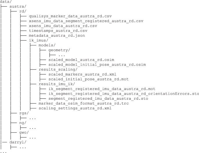
Structure of the dataset directory. Example folder layout for one participant and exercise, including raw data, model files, and results from scaling and Inverse Kinematics.
Once the full transformation chain has been applied, the resulting segment-aligned orientations can be used as input to compute joint angles via the IMUInverseKinematicsTool. The resulting joint angle trajectories reflect the recorded motion in anatomically interpretable form and provide a valuable basis for subsequent analysis and visualization Fig. 6. All joint angle trajectories, error estimates and configuration files required to rerun the Inverse Kinematics procedure, are included in the dataset. This allows users to either directly inspect the results or modify and reproduce the processing pipeline according to their own requirements.
link