
Over three hours of marker-based and marker-less motion was captured with ethical approval from the University of Liverpool research ethics committee (Reference #10259). Participants provided full consent, via a signed consent form, in sharing and using their anonymised data through the University of Liverpool Data Catalogue to support other future research.
Subject recruitment
Healthy adults are defined as adults who can complete the full range of motions for all exercises within the UL-RED dataset, with no musculoskeletal problems that limit this. The main exclusion criteria are that subjects did not have any injuries that affected normal biomechanics within the last six months and they did not have any dangerous medical conditions or any conditions potentially limiting biomechanics such as asthma, chronic injury, or pregnancy.
Table 2 shows the height, arm span, and sex of each subject. Male subjects had an average height of 1.80 ± 0.12 m with an average arm span of 1.53 ± 0.12 m. Female subjects have a lower average height of 1.67 ± 0.03 m with also a lower average arm span of 1.40 ± 0.05 m. All subjects had an average height of 1.73 m and an average arm span of 1.47 m. Height measurements were collected from the y-axis positional data of the head marker, which is located at the highest point on the subject’s skull. Arm span was calculated by computing the Euclidean distance between the left and right palm marker 3D position. These two measurements were taken while the subjects were in the T-Pose.
All subjects were instructed on specific clothing requirements prior to their allocated session to ensure optimum marker-based and marker-less tracking. This included avoiding dark coloured and loose fitting clothes, wearing collarless and sleeveless t-shirts, wearing low cut shoes and socks, and long hair had to be tied up using hair bobbles provided on the day. To allow for head marker placement, each subject was provided with a black motion cap. The participant information sheet describing all aspects of the data collection study, visual motion descriptions of the exercises the subjects have to perform, and the consent form that will be signed on the day were sent one week prior to data collection for subjects to get familiarised with.
Exercise selection
For this data collection, non-specialised rehabilitation exercises were selected. These exercises are low risk movements that can be performed by patients safely in the comfort of their homes. This selection of upper body, lower body, and whole body exercises are commonly seen in the rehabilitation space, especially for older individuals. 22 exercises were selected based on publicly available exercise guidance by the National Health Service (NHS) in the United Kingdom (UK) (www.nhs.uk/live-well/exercise/physical-activity-guidelines-older-adults), and using insight from shadowing sessions at a local frailty therapy ward. This selection consisted of 6 seated and 16 standing movements, performed across all three body planes of movement: coronal, sagittal, and transverse. Table 3 defines the 22 exercises along with a short description of the movement. For each exercise recording, subjects were instructed to perform a T-Pose at the start and end of each recording. For asymmetric repetitions, such as the knee raise, subjects were instructed to perform with the left side first and then the right side. All exercises describe static movements, apart from FullFrontalsidewaysStep, where the subject’s whole body does not leave the original position in the room. For each motion, a single repetition and three-time varied repetitions were collected. The latter collected subjects performing the motion at a normal, fast, and slow pace, in that order. Subjects were guided to perform these three speeds by their own intuition.
Marker motion capture
Marker data was captured using an OptiTrack (NaturalPoint Inc., Corvallis, USA) system with eight infrared OptiTrack 17 W Prime cameras placed at each vertex of a 4.4 by 5 meter recording area, capturing marker data at a sample rate of 250 Frames Per Second (FPS). At each vertex, two Prime cameras are placed at 1 meter and 1.9 m from the floor to provide a wide field of view. Camera view angles were manually adjusted to ensure the lower cameras captured the lower body movements and upper cameras capture all upper body movements. To ensure this capture volume, and to align with the limited capture volume of the marker-less motion tracking system, a 2 by 2 meter capture area was setup at the centre of the recording area. Figure 2 shows the marker-based and marker-less sensor setup alongside the capture area location. To aid subjects in performing the exercises, a digital display was placed in the subjects’ view projecting the real-time marker-less motion tracking data. This not only helped ensure optimal motion tracking by both the subject and data collector, but also as a visual aid in ensuring correct exercise form.
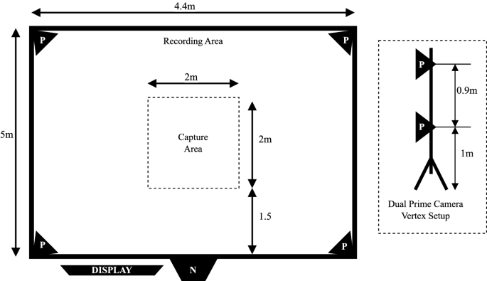
OptiTrack infrared camera (denoted by P) setup, recording area and capture area dimensions, and positions of the marker-less sensor (denoted by N). At each corner of the recording area, denoted by P, two Optitrack 17 W Prime cameras were setup facing the capture area. The vertical Optitrack camera setup ensured every marker was captured by at least three cameras to enable 3D reconstruction using the Optitrack Motive software. The marker-less sensor, Orbbec Persee, is placed at the midpoint of the longest side of the recording area, facing directly towards the capture area. The marker-less tracking output was then displayed in real-time using a digital display that participants can use to aid in their data capture. The capture area was significantly smaller than the recording area due to the space constraints of the marker-less tracking system.
To capture the subject’s movements, 29 retro—reflective markers were attached either directly on their skin using skin friendly adhesives or over clothed areas using tightly wrapped elastic cloth, following the marker layout in Fig. 3. To ensure consistency of marker placements between subjects, great care was taken to place markers using skeletal reference points where possible. For markers that do not directly reference such points, such as the waist marker, visual references were used to determine the correct placement, e.g. using the position of the left and right hip markers. The reference points used for all 29 markers are shown in Table 4. This marker layout was chosen to represent a similar but unique skeletal definition to existing marker-less motion tracking systems.

The marker placement of all 29 markers used to capture marker motion data with the OptiTrack system. Markers were placed by the data collector using skeletal and visual landmarks to allow for the capture of joint centres at a later stage. These markers were selected to represent skeletal pose layouts similar to ones seen from marker-less systems. All markers were attached either directly to the skin using skin friendly adhesives or on elastic cloth wrapping for areas such as the left hip joint. The head joint marker was attached onto a motion capture cap the participants wore.
Before each subject’s recording session, a two-stage camera calibration is performed following the OptiTrack guidelines. This consisted of a 3D position and orientation calibration using the passive OptiTrack CW-500 wand, and a ground plane calibration using the OptiTrack CS-200 calibration square. All calibration and data capture were performed using the accompanying software Motive version 2.1.1.The coordinate systems origin point is at the centre of the capture area, on the floor, with the positive z axis facing away from the marker-less camera (refer to Fig. 2), positive y axis directed upwards from the origin point, and positive x axis directed towards the left of the marker-less camera (when facing in the direction of the positive z axis).
Marker data post-processing
Once the marker data has been collected, it is first labelled and cleaned following the marker labels in Fig. 3. The first visible frame is selected and each marker is labelled manually. With this reference frame, the Motive software then attempts to automatically label markers across all frames. Commonly, there are gaps in tracking data from occlusions or mislabelling from the automated process. Unlabelled markers are corrected by manually traversing the frames and labelling data where possible. Missing marker data, under 500 successive frames, are filled using the Motive linear interpolated gap filler tool. For marker data that exceed this gap, the Motive pattern based interpolator is used which interpolates a marker position based on two neighbouring markers. This assumes that the neighbouring points form a rigid body, which can be made for skeletal data. For example, the LElbow1 marker data can be interpolated using this approach by referencing both LElbow2 and LWrist1 markers. Once all data is labelled and cleaned, they are exported as a Comma Separated Value (CSV) file.
The raw marker data is then transformed into the pose definition shown in Fig. 4. For the head, left shoulder, right shoulder, left palm, and right palm markers, a direct transformation is performed. This copies the 3D marker position using the mapping
$$f:\left(x,y,z\right)\to (x,y,z)$$

The resulting 18 joint skeletal definition after transforming the marker data. The marker-based data were used to calculate the joint centers that replicated the 3D positions outputted by marker-less tracking systems. The head marker and palm markers performed a one-to-one mapping of its position for the head and palm joints. The hip joints were computed using the midpoint of the hip, and both waist markers (Waist1 and Waist2). All other joint positions were computed using the midpoint between two markers.
For all other marker pairs, denoted by either 1 or 2 in its suffix, excluding left hip and right hip, a pairwise transformation is performed. The corresponding joint position in Fig. 4 is calculated from the midpoint between two 3D marker positions using the mapping
$$f:\left({v}_{1},{v}_{2}\right)\to \left(\left(\frac{{v}_{1}^{x}+{v}_{2}^{x}}{2}\right)+\left(\frac{{v}_{1}^{y}+{v}_{2}^{y}}{2}\right)+\left(\frac{{v}_{1}^{z}+{v}_{2}^{z}}{2}\right)\right)$$
Where vx denotes a 3D position vector containing x, y, and z positional values. For the left and right hip joints, the midpoint between each hip marker and the Waist1 and Waist2 markers were calculated. This is simply an extension of the pairwise transformation
$$f:\left({v}_{1},{v}_{2},{v}_{3}\right)\to \left(\left(\frac{{v}_{1}^{x}+{v}_{2}^{x}+{v}_{3}^{x}}{3}\right)+\left(\frac{{v}_{1}^{y}+{v}_{2}^{y}+{v}_{3}^{y}}{3}\right)+\left(\frac{{v}_{1}^{z}+{v}_{2}^{z}+{v}_{3}^{z}}{3}\right)\right)$$
These three processes completes the transformation of the marker layout shown in Fig. 3 to the skeletal layout shown in Fig. 4.
Finally, a T-Pose crop is performed to ensure all recordings start and end with a T-Pose. Although great care was taken to ensure subjects always started and ended in a T-Pose, there were situations where a T-Pose was held for a long period of time. This stores unnecessary and duplicate motion data that does not contribute to the captured exercise. Hence, a walking T-Pose cropping algorithm is implemented which traverses the data forwards and in reverse to perform this crop. A T-Pose is defined by the angle between the spine vector, defined by the waist and head joints, and four vectors defined by the joint pairs: left shoulder and left wrist, right shoulder and right wrist, left hip and left ankle, right hip and right ankle. A T-Pose requires an angle of 90 degrees ± 10 degrees between each arm and spine vector, and 180 degrees ± 10 degrees between each leg and spine vector. Figure 5 presents the pseudo code of the implemented walking T-Pose cropping algorithm. The FindTPose function calculates if a skeletal frame is in the T-Pose using the previously defined angular constraints. This function is then iterated through frames until the last T-Pose is found. This walking method is performed forwards from the first frame with a step of one, and backwards from the last frame with a step of negative one. This method is also applied during the marker-less motion data post-processing which can aid in the synchronisation of the two motion data. The skeletal motion data is than stored in the Acclaim Motion Capture (AMC) file format which is detailed in the Data Records section.

Pseudo code of the T-Pose cropping algorithm used to trim both marker and marker-less motion data. To find a T-Pose, the angle between the spine vector, defined by the vector between the waist and head joints, and both the left and right arms and legs vectors were used. The arm vectors were defined as the vector between the shoulder and wrist joints. The leg vectors were defined as the vector between the hip and ankle joints. A pose was considered to be in the T-Pose if the angle between the arms and spine were 90 degrees ± 10 degrees, and the angle between the legs and spine were 180 degrees ± 10 degrees.
Marker-less & depth motion capture
Marker-less motion data was captured at a sample rate of 30 FPS using the Nuitrack 3D skeletal tracking library (Cvartel Inc., Covina, USA) that uses depth data to recognise skeletal poses in real time. The depth data was captured using the Orbbec Persee (Orbbec Inc., Shenzhen, China) depth camera computer version one. The Nuitrack library tracks a 19 joint skeletal pose shown in Fig. 6, with each joint defined by its 3D position relative to the depth sensors origin. Although the Nuitrack system can be paired with a wide variety of depth sensors, the Orbbec Persee version one was chosen due to its optimal depth tracking and onboard computing unit that can host the Nuitrack library. The depth data was collected simultaneously with the marker-less motion data, at a resolution of 160 by 120 pixels at 16 bit. Although all related datasets used the Microsoft Kinect for marker-less motion tracking (refer to Table 1) the decision to not use the Kinect was due to its deprecated hardware and software, which is a barrier to future use.

The Nuitrack marker-less 19 joint skeletal definition. The location of all joint 3D positions provided by the Nuitrack marker-less tracking system. This method of joint tracking uses infrared depth data that allows for real measurement of the depth of each joint position. This computation is performed in real-time and on the Orbbec Persee depth camera device used for the marker-less data collection.
To collect marker-less motion data and depth data using the Nuitrack library and the Orbbec Persee depth camera, a custom Android mobile application was developed using the Unity game engine which ran on the Orbbec Persee onboard computing unit. Figure 7 shows the recording screen of this application which was also displayed to the subjects using a digital display, as shown in Fig. 2.

Nuitrack based marker-less motion tracking Android application running on the Orbbec Persee on board computing unit. This Android based application was developed to run on the Orbbec Persee platform to both aid in the capture of human motion data and provide visual aid to participants during data collection. This platform was interacted with remotely via an ethernet connection and the Android Debug Bridge (ADB) on the computing unit hosting the Optitrack Motive software. A unique filename was required to begin tracking, entered within the white text box. All files were saved locally on the device temporarily before transferring to their final secure research drive location.
The data collection implemented all the recommendations provided by the Nuitrack library for optimal marker-less motion tracking. The tracking area did not have direct sunlight exposure. The Orbbec Persee depth camera was placed at a height of 1.2 m from the floor. The capture area was between 1.5 and 3 m from the Orbbec Persee depth camera. The surrounding walls and ceilings of the capture area must have a gap of at least 40 cm. Finally, subjects were asked to avoid dark coloured clothing which can negatively impact motion tracking.
Marker data post-processing
A three stage outlier filtering process is applied to reduce the effects of skeletal tracking errors where possible. In certain situations, the Nuitrack library would produce skeletal tracking joints with low confidence, which resulted in the joint position not being tracked. Such situations were recorded in the data collection stage as zero value 3D vectors. From visual inspection, there were tracking errors resulting in incorrect joint placements for certain intervals of time. The authors assume these errors are caused mainly by body occlusions but it is difficult to further evaluate this as the Nuitrack library code base is closed source.
The walking T-Pose cropping algorithm discussed previously, and defined in Fig. 5, was first applied to ensure every recording starts and ends in a T-Pose. This also helps aid in synchronisation between marker-based and marker-less motion data. Then, any joints that exceed their skeletal bone lengths in reference to their parent joint, excluding the waist joint, is labelled as not tracked using a zero value 3D vector. The bone lengths are referenced from the first T-Pose frame of each recording and outliers are found if their bone lengths are greater than a factor of 1.01 or less than a factor of 0.99. This 1% tolerance ensures consistent tracking across each frame, at 30 FPS each frame is captured every 33.33 milliseconds hence deviations greater that 1% can be an indication of inaccurate tracking.
These outliers, in addition to the untracked joints by Nuitrack, are filled using a forward fill approach in two passes. The first pass fills the outliers found by Nuitrack, then the second pass fills outliers found using the bone length method. The forward fill method takes the last valid tracked position of the joint and duplicates it across the consecutive outlier frames. This is performed in order of the joint hierarchy, starting with the root joint set to the waist joint. These steps attempts to fix most of the tracking errors contained in the marker-less data. However, it is not guaranteed to fix every tracking artefact produced.
Data collection process
The marker-based and marker-less setup was presented in Fig. 2, with subjects performing exercises within the specified capture area. Figure 8 shows the real setup following the layout shown in Fig. 2. However, the OptiTrack and Nuitrack systems tracked motion in two isolated computing environments with no direct hardware synchronisation capabilities. To help synchronise these the marker-based, marker-less, and depth data, subjects performed the T-Pose at the start and end of each recording, in addition to automating the start of the data capture using mouse movement macros. This was achieved using the Auto Mouse Clicker by MurGee (Daanav Softwares, Goa, India) software which performed preset on-screen mouse interactions with a minimum delay of approximately 1 millisecond. To allow for this automated start, the Nuitrack recording application, shown in Fig. 6, hosted on the Orbbec Persee computing unit was streamed to the desktop computer hosting the OptiTrack Motive software using a direct ethernet connection, with the Android Debug Bridge (ADB), and the scrcpy library (www.github.com/Genymobile/scrcpy). Although great effort was taken to ensure synchronisation using this software-based approach, it is not guaranteed that both data modalities are perfectly synchronised.

The OptiTrack (marker-based) and Nuitrack (marker-less) capture environment used in the UL-RED data collection study. This follows the same layout description in Fig. 2. All cables were routed to ensure low risk to participants during entry to and exit from the capture arena. The capture area was situated in a closed room with no direct sunlight to ensure minimal interference to both the marker-based and marker-less systems.
link